Wave i4 DC (EU)
Note: The product line known as "Shelly Qubino Wave" will now be referred to as "Shelly Wave". This name change will not impact the functionality of any devices. The only modification will be the use of the new name in all future documentation.

Device: Wave i4 DC
EU Part number/Ordering Code: QNSN-0D24XEU
Z-Wave Product type ID: 0x0009
Z-Wave Product ID: 0x0082
Z-Wave Manufacturer: Shelly Europe Ltd.
Z-Wave Manufacturer ID: 0x0460
Terminology
Device - In this document, the term “Device” is used to refer to the Shelly Qubino device that is a subject of this guide.
Gateway - A Z-Wave® gateway, also referred to as a Z-Wave® controller, Z-Wave® main controller, Z-Wave® primary controller, or Z-Wave® hub, etc., is a device that serves as a central hub for a Z-Wave® smart home network. The term “gateway” is used in this document.
S button - The Z-Wave® Service button, located on Z-Wave® devices and is used for various functions such as adding (inclusion), removing (exclusion), and resetting the device to its factory default settings. The term "S button" is used in this document.
Adding/Inclusion - The process of adding Z-Wave device to a Z-Wave network - gateway. The words included, added, etc. are used in this regard.
Removing/Exclusion - The process of removing Z-Wave device from a Z-Wave network - gateway. The words excluded, removed, etc. are used in this regard.
Blind - Refers to any kind of window treatment, such as venetian blinds, roller blinds (screens), roller shutters, vertical window blinds, curtains, integral venetian blinds, pleated blinds, awnings, etc. Additionally, Wave Shutter can also control window motors, projector screens, or any type of bi-directional AC motor.
Short description
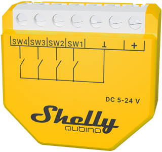
The Device is a 4-digital inputs module (5 - 24 V DC) that controls other devices within the Z-Wave network. It enables manual activation or deactivation of scenes through a switch/push-button.
Switch/push-button connected to input terminal SW1
The device supports Central Scene Command Class and when a button is single pressed, double pressed, held and released, it will transmit a scene notification together with scene number (1,2,3 or 4)
NOTE: Switch type is not supported for triggering central scene notifications
Push-button connected to input terminal SW1
If the SW1 is configured as a push-button:
Scene number = 0X01
Short press: Central scene notification “Key pressed 1 time=0x00” with scene number 0X01 is sent and send command to the associated devices in associated groups 4 (check chapter Z-Wave Association).
2x Short press: Central scene notification “Key pressed 2 time=0x00” is sent.
Press and hold: Central scene notification “Key held down =0x02” is sent and Send command to the associated devices in associated group 5 (check chapter Z-Wave Association).
Release: Central scene notification “Key released =0x01” is sent and Send command to the associated devices in associated group 5 (check chapter Z-Wave Association).
If the SW1 is configured as a switch:
Change switch position once: Send the command to the associated devices in associated groups 4 and 5 (check chapter Z-Wave Association).
If the SW1 is configured as a switch-memory:
Switching to Close switch-memory contact: send command to the associated devices in associated groups 4 and 5 (check chapter Z-Wave Association) according to switch state.
Switching to Open switch-memory contact: send command to the associated devices in associated groups 4 and 5 (check chapter Z-Wave Association) according to switch state.
Switch/push-button connected to input terminal SW2
If the SW2 is configured as a push-button:
Scene number = 0X02
Short press: Central scene notification “Key pressed 1 time=0x00” with scene number 0X02 is sent and send command to the associated devices in associated groups 6 (check chapter Z-Wave Association).
2x Short press: Central scene notification “Key pressed 2 time=0x00” is sent.
Press and hold: Central scene notification “Key held down =0x02” is sent and Send command to the associated devices in associated group 7 (check chapter Z-Wave Association).
Release: Central scene notification “Key released =0x01” is sent and Send command to the associated devices in associated group 7 (check chapter Z-Wave Association).
If the SW2 is configured as a switch:
Change switch position once: Send the command to the associated devices in associated groups 6 and 7 (check chapter Z-Wave Association).
If the SW2 is configured as a switch-memory:
Switching to Close switch-memory contact: send command to the associated devices in associated groups 6 and 7 (check chapter Z-Wave Association) according to switch state.
Switching to Open switch-memory contact: send command to the associated devices in associated groups 6 and 7 (check chapter Z-Wave Association) according to switch state.
Switch/push-button connected to input terminal SW3
If the SW3 is configured as a push-button:
Scene number = 0X03
Short press: Central scene notification “Key pressed 1 time=0x00” with scene number 0X03 is sent and send command to the associated devices in associated groups 8 (check chapter Z-Wave Association).
2x Short press: Central scene notification “Key pressed 2 time=0x00” is sent.
Press and hold: Central scene notification “Key held down =0x02” is sent and Send command to the associated devices in associated group 9 (check chapter Z-Wave Association).
Release: Central scene notification “Key released =0x01” is sent and Send command to the associated devices in associated group 9 (check chapter Z-Wave Association).
If the SW3 is configured as a switch:
Change switch position once: Send the command to the associated devices in associated groups 8 and 9 (check chapter Z-Wave Association).
If the SW3 is configured as a switch-memory:
Switching to Close switch-memory contact: send command to the associated devices in associated groups 8 and 9 (check chapter Z-Wave Association) according to switch state.
Switching to Open switch-memory contact: send command to the associated devices in associated groups 8 and 9 (check chapter Z-Wave Association) according to switch state.
Switch/push-button connected to input terminal SW4
If the SW4 is configured as a push-button:
Scene number = 0X04
Short press: Central scene notification “Key pressed 1 time=0x00” with scene number 0X04 is sent and send command to the associated devices in associated groups 10 (check chapter Z-Wave Association).
2x Short press: Central scene notification “Key pressed 2 time=0x00” is sent.
Press and hold: Central scene notification “Key held down =0x02” is sent and Send command to the associated devices in associated group 11 (check chapter Z-Wave Association).
Release: Central scene notification “Key released =0x01” is sent and Send command to the associated devices in associated group 11 (check chapter Z-Wave Association).
If the SW4 is configured as a switch:
Change switch position once: Send the command to the associated devices in associated groups 8 and 9 (check chapter Z-Wave Association).
If the SW4 is configured as a switch-memory:
Switching to Close switch-memory contact: send command to the associated devices in associated groups 10 and 11 (check chapter Z-Wave Association) according to switch state.
Switching to Open switch-memory contact: send command to the associated devices in associated groups 10 and 11 (check chapter Z-Wave Association) according to switch state.
Main applications
Residential
MDU (Multi Dwelling Units - apartments, condominiums, hotels, etc.)
Light commercial (small office buildings, small retail/restaurant/gas station, etc.)
Government/municipal
University/college
Integrations
Shelly Qubino Wave devices are developed on the world's leading technology for smart homes – Z-Wave.
This means Shelly Qubino Wave works with all certified gateways supporting Z-Wave communication protocol.
To make sure the functions of Shelly Qubino Wave products are supported on your gateway, we are regularly executing compatibility tests of our devices with different Z-Wave gateways. Please refer to the reports available in the 'Compatibility with Gateways' section below for detailed information on compatibility status.
Simplified internal schematics
N/A
Device electrical interfaces
Inputs
1 switch/button input on screw terminal
2 switch/button inputs on screw terminal
3 switch/button inputs on screw terminal
4 switch/button inputs on screw terminal
3 power supply inputs on screw terminals: N, L
Outputs
N/A
Connectivity
Z-Wave - Unsecure, S0 Security, S2 Unauthenticated Security, S2 Authenticated Security
Safety features
Overheat protection
switch off its own relay
sends the Notification Report to the Gateway (Overheat detected)
the led lights react as specified above (check blinking mode for Overheat detected)
Any of next activities reset this alarm: power cycle, short press on S button, press any switch-push button connected to any SW (SW, SW1, SW2, …) terminal.
NOTE: The Overheat protection is always active and cannot be disabled.
Additional description above under chapter Notification for Overheat detected.
Supported load types
N/A
User interface
S button and operating modes
Normal mode
Setting in progress mode
-
Setting mode (with S button)
Settings mode is required to start desired procedure for example: adding (inclusion), removing (exclusion), factory reset etc. It has a limited time of operation. After the procedure in Setting mode is concluded, the Device goes automatically into Normal mode.
-
Entering to Setting mode:
Quickly press and hold the S button on the Device until the LED turns solid blue
An additional quick press on the S button means menu change in infinite loop
Menu LED status has a timeout of 10s before entering again into Normal state
S button’s functions
Manually adding the Device to a Z-Wave network
Manually removing the Device from a Z-Wave network
Factory Reset the Device
LED Signalisation
LED blinking modes
Specifications
Power supply AC |
No |
Power supply DC |
5 - 24 V DC |
Power consumption |
< 0.3 W |
Overload protection |
No |
Power measurement |
No |
Number of inputs |
4 |
Distance |
Up to 40 m indoors (131 ft.) (depends on local condition) |
Z-Wave® repeater: |
Yes |
CPU |
Z-Wave® S800 |
Z-Wave® frequency band: |
868,4 MHz |
Maximum radio frequency power transmitted in frequency band(s) |
< 25 mW |
Size (H x W x D) |
37x42x16 ±0.5 mm / 1.46x1.65x0.63 ±0.02 in |
Weight |
17 g / 0.6 oz |
Mounting |
Wall box |
Screw terminals max. torque |
0.4 Nm / 3.5 lbin |
Conductor cross section |
0.5 to 1.5 mm² / 20 to 16 AWG |
Conductor stripped length |
5 to 6 mm / 0.20 to 0.24 in |
Shell material |
Plastic |
Color |
Yellow |
Ambient temperature |
-20°C to 40°C / -5°F to 105°F |
Humidity |
30 % to 70 % RH |
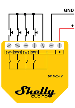
Basic wiring diagram
 |
 |
Legend
Terminals |
|
Wires |
|
|---|---|---|---|
ꓕ |
5 - 24 V DC ground terminal |
GND |
5 - 24 V DC ground wire |
+ |
5 - 24 V DC positive terminal |
+ |
5 - 24 V DC positive wire |
SW 1 |
Switch/push-button input terminal |
||
SW 2 |
Switch/push-button input terminal |
||
SW 3 |
Switch/push-button input terminal |
|
|
SW 4 |
Switch/push-button input terminal |
|
|
About Z-Wave
Adding the Device to a Z-Wave® network (inclusion)
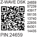
Z-Wave Security and Device Specific Key (DSK)
Z-Wave Parameters
Z-Wave Command Class
Z-Wave Notifications Command Class
Z-Wave Associations
Z-Wave Important disclaimer
Z-Wave® wireless communication may not always be 100% reliable. This Device should not be used in situations in which life and/or valuables are solely dependent on its functioning. If the Device is not recognised by your gateway or appears incorrectly, you may need to change the Device type manually and ensure that your gateway supports Z-Wave Plus™ multi-level devices.
Troubleshooting
For troubleshooting please visit our support portal: https://support.shelly.cloud/
Compatibility with gateways
The device send Central Scene Notification command, which can be used in automation. Another way of using the device is with the direct association or use the On Off reports of the SW1 - SW4.
Wave i4 DC | |||||
Gateway |
On/Off 1 |
On/Off 2 |
On/Off 3 |
On/Off 4 |
Notes |
Home Assistant |
|
|
|
|
|
Fibaro HC 3 / Z-Wave engine 3 |
|
|
|
|
|
Homey |
|
|
|
|
Troubles with reports can be solved with this solution. |
Homee Cube Gen 7 |
|
|
|
|
|
Homee Cube Gen 5 |
❌ |
❌ |
❌ |
❌ |
not possible to use the central scene in automation either or association, no use for this gateway. |
Smart Things |
|
|
|
|
|
Jeedom |
TBD |
TBD |
TBD |
TBD |
|
Hubitat |
TBD |
TBD |
TBD |
TBD |
|
Notes |
|||||
Function |
Meaning / tested |
|---|---|
On/Off |
if device respond to the app UI On/Off command |
SW On/Off |
if device reports On/Off changes by SW input |
Dimming |
if device respond to app UI dimming command |
SW Dimming |
if device report dimming state change by SW input |
Watts |
if Watts are reported (unsolicited) |
kWh |
if kWh are reported (unsolicited) |
Up/Down |
if device respond to the app UI Up/Down command |
SW Up/Down |
if device reports Up/Down changes by SW input |
Slats |
if the slats respond to the app UI command |
SW Slats |
if the slats report the changes done by SW |
*SW scene |
detached mode if device reports scene commands single press, double press,… |
*SW On/Off |
detached mode if the device reports binary On/Off by SW input |
Legend | ||||
Symbol |
State |
|||
|
Working / Possible |
|||
❌ |
Not Working / Not Possible |
|||
P |
Partially |
|||
N/T |
Not Tested |
|||
TBD |
To be done |
|||
Gateway guides
You may find useful guides on gateways in the Z-Wave Shelly Knowledge base.
Compliance
Wave i4 DC multilingual EU declaration of conformity.pdf
Wave i4DC UK PSTI ACT Statement of compliance.pdf


